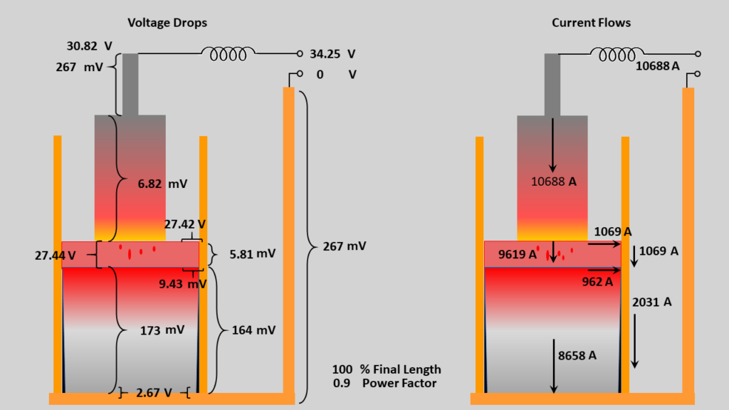
Based on user-specified furnace resistances and calculated resistances of the electrode, ingot, and crucible, the remelt simulator calculates various current flows and voltage drops throughout the furnace. An EI (voltage-current) plot showing the voltage and current distribution within the furnace may be generated from within VARsim.
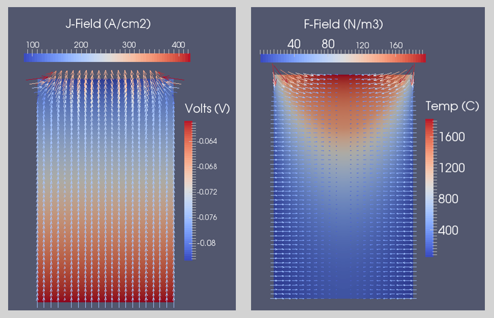
From these results, electromagnetic parameters within the ingot domain are calculated and used to generate CSV and VTK files for further analysis. Vector fields for electric potential, current density, and Lorentz force may be plotted on a background scalar field of temperature, voltage, or vector magnitude.
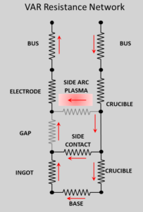
The calculation of voltages and currents throughout an ESR furnace is complicated by the diverse possible electrical configurations and current paths within the process. The resistance networks for some basic configurations for “live” mold and “insulated” mold cases, for both static and withdrawal crucibles are displayed below.
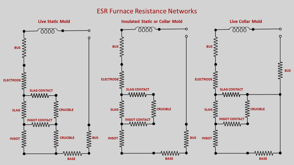
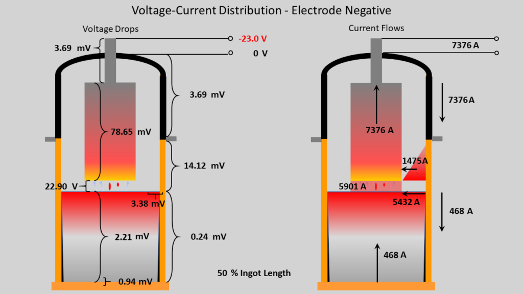
In each case, it is assumed that there is a path for current flow from the slag to the crucible (across the surface of the slag) and between the ingot and the crucible (at the slag-ingot interface). Each of these currents can be specified as a percentage of the electrode current (for the slag-crucible contact) and a percentage of the slag current (for the ingot-crucible contact) which then allows the voltage-current distribution to be determined. The results can be displayed as shown in the figure below.