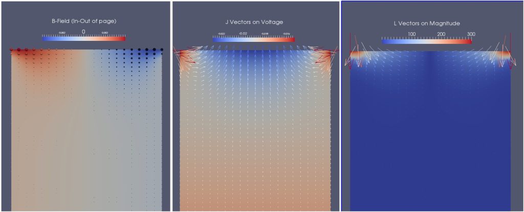
Due to the current paths in a typical VAR melt, the interaction of the self-generated magnetic field and the current field (J x B) leads to a Lorentz force field which acts on the liquid metal pool as shown below.
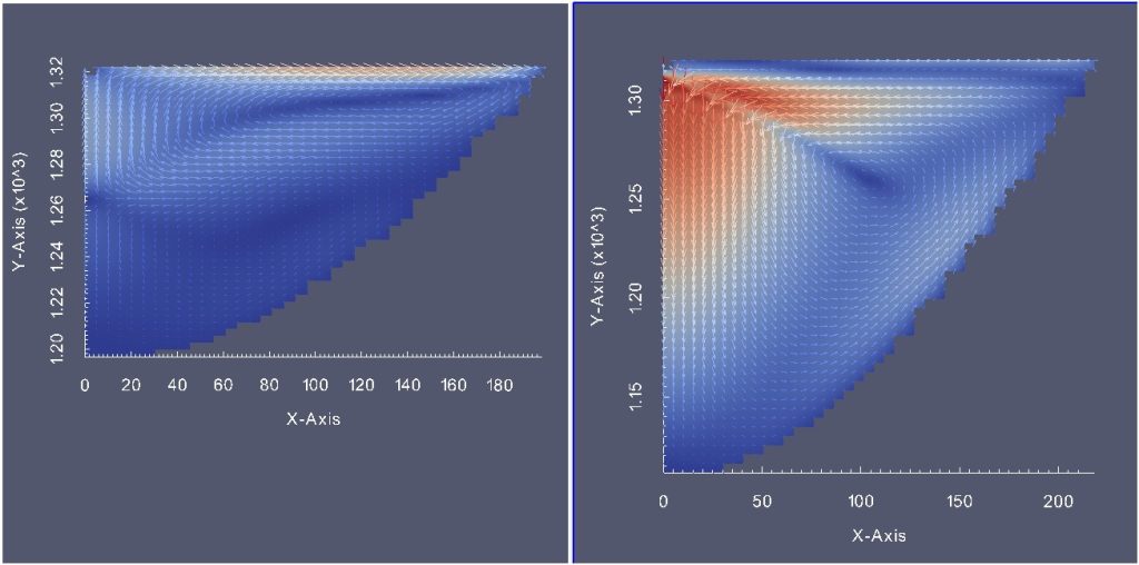
The fluid flow module solves the Navier Stokes equations for laminar flow conditions in order to provide an indication of the direction of fluid flow and whether or not this may be problematic for ingot quality. An example of this is the application to two scenarios presented in the literature – melting a 508 mm diameter ingot of alloy 718 at 6000 A and 8600 A respectively.
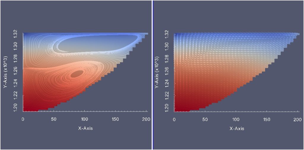
The figures above show the flow results at 6000 A which reveal two recirculating flow zones, an upper clockwise flow zone and a lower counterclockwise zone.

The flow pattern at 8600 A again reveals two flow zones, a much smaller upper clockwise zone and a lower more dominant counter-clockwise zone. When these results are plotted with the same velocity scales on a field of the velocity magnitude, the results reveal the dramatic difference in flow regimes. The fluid velocities in the 6000 A practice are much lower than in the 8600 A practice with the result that the latter practice reveals hot liquid being driven from the upper regions of the pool down to the lower levels producing a deeper pool than might otherwise be expected. This would indicate a practice that might be problematic to ingot quality.